From the very beginning, the Laboratory of Internal Flows in Nový Knín has served as a research basis for the Division of Gas Dynamics, and partly also for the Division of Turbulence and Boundary Layers, or the Division of Systems Dynamics. The first two divisions merged in 1990 into one Division of Fluid Dynamics. At the same time the Laboratory was being expanded by the wind tunnel for atmospheric boundary layer simulation and blowdown facility for investigation of impinging jets.
Research in the Gas Dynamics Division has been carried out along two lines
- fundamental research of transonic flow in closed channels and in turbomachinery cascades [11]
- experimental investigation of transonic and supersonic flow in compressor and turbine cascades, incl. measurements on contract with our industry (ŠKODA concern, PBS Brno and Velká Bíteš, MOTORLET)
Fundamental research was concerned with a detailed study of development and structure of phenomena characteristic of transonic and supersonic flow in 2D axial, as well as radial cascades. The problem of starting a supersonic cascade was studied in detail. For the first time we have shown how the system of front shock waves in a supersonic cascade develops [12], and how it affects the flow structure in the cascade. Experiments were carried out on a cascade of double-circular-arc symmetric profiles, and the results have become a standard for validation of CFD methods developed in our Institute, as well as in institutes abroad (Fig. 1). These measurements were also confirmed by a high-speed camera, by recording interferogrammes of the whole process of starting supersonic flow in a cascade.
 1. Development of a set of fornt and closing shock waves in a blade cascade.
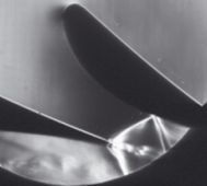
Experiments on a supersonic compressor cascade have also visualized the unsteady process of transition from the started to unstarted regime in a supersonic compressor cascade (Fig. 2).
 |
 |
| 2. Supersonic flow past compressor blade cascade. |
3. Analysis of propagation and reflection of characteristics in local supersonic region. |
At the beginning of the seventies, the problem of aerodynamic optimization of turbomachinery cascades was one of the main topics investigated theoretically and experimentally by the Gas Dynamics Group [13], (Fig.3). It also included a detailed study of the origin and development of shock waves in the leading edge region, and in the trailing edge region, as well as interaction of the shock waves with boundary layers, other shock waves and simple waves, incl., e.g., attenuation of shock waves by expansion regions [15]. The results obtained were used in optimizing the tip sections of the turbine cascades for the last stages of large steam turbines for nuclear power plants. Reshaping the leading edge of the 1077mm long blade (ŠKODA turbines of 500 MW and 1000 MW output) decreased the losses in the design point , i.e., at M2is ~ 1.8 , by almost 30% [15].
Since the cascade wind tunnel was made operational 40 years ago, almost 100 various turbine and compressor cascades have been tested in detail. New and original results have been obtained, contributing substantially to our knowledge of transonic and supersonic flow in cascades. At the same time new measurement methods and technique for transonic cascade testing were developed. The Laboratory has become one of the few laboratories in the world capable of testing cascades at M1 ~ 1.
The extensive experimental programme covered a detailed and systematic investigation of numerous turbine rotor cascades in the range 0.3 < M1 < 0.9, M2is ~ up to 1.95 . Only the investigation of the last stage of the 1000 MW steam turbine represents about 1000 of evaluated optical measurements. Recently, a considerable part of the archive of interferogrammes and schlieren pictures was digitalized e.g. [16], and is now available in the Institute in electronic form.
The turbine rotor cascades were tested also at extreme incidences (e.g. Fig.38). It has been observed that the displacement effect of the leading edge separation bubble on the blade pressure side can change the effective shape of the blade so that the pressure is lower there than on the other side of the blade, thus changing the direction of the resulting aerodynamic force (Figs.4, 5).
 |

|
| 4. Interferograms of a turbine cascade at extreme incidence angles. |
5. Displacement effect of the leading edge separation bubble. |
The experimental programme covered also investigation of the supersonic flow in inducers of centrifugal impellers e.g.[18] (Fig.6).
 6. Interferogram of a cascade of transsonic inducer of centrifugal impeller.
For the first time ever, a detailed experimental investigation of transonic flow in radial-inflow-turbine cascades has been carried out (Fig. 7). As the blades are of very low aspect ratio, it has been necessary to take all the threedimensional effects into account. To make this research possible it has been necessary to revise the method of testing and evaluating the aerodynamic characteristics of the cascades, and to adapt the test section to make also the optical measurements possible [19].
 |
 |
| 7. Schlieren picture of a radial blade turbine stator cascade. |
8. Pseudoshock wave in a 10mm wide channel. |
The long term research programme comprises also systematic investigation of transonic and supersonic flow in the so called relatively narrow channels, as, e.g., diffusers of centrifugal compressors, or radial turbine cascades. This flow is inherently threedimensional, affected by aerodynamic choking, and by all viscous flow effects, like threedimensional flow separation, secondary flows, strong viscous-inviscid interaction, etc. e.g. [20], [21], [22], [23], [24]. One of the important problems solved was the transition from supersonic to subsonic velocities in these channels, which often takes place in a train of shock waves, the so called pseudoshock wave. Its origin and development was experimentally investigated e.g. [25], [26]. Fig. 8 shows a closure of a local supersonic region in a narrow channel, where the terminal shock wave is substituted by a pseudoshock wave.
Since 1960, the Gas Dynamics Group has been engaged in theoretical and experimental investigation of unsteady transonic flows e.g. [27], [28], and in the origin and implications of transonic instability. The experimental investigation was carried out in the Aerodynamics Laboratory in Nový Knín e.g. [29], [30], [31]. The wind tunnel for cascade research was adjusted for measurements of symmetric transonic flow past isolated airfoils (NACA0012, and a symmetric double-circular-arc profile with 18% relative thickness), and for studying gradual growth of the terminal shock wave and its stability against disturbances generated in the wake. The shock wave movement was traced in a streamwise-oriented slit above the airfoil by a fast streak camera [29]. The upstream propagation of disturbances, or propagation of disturbances around the airfoil in the subsonic part of the boundary layer, were also studied e.g., [31], together with means of preventing this movement (e.g., by splitter plates on leading or trailing edges) and its implications on the flow stability.
Further to the investigation of flow past blunt trailing edges [32] extensive experimental research of the flow past plugs of large regulating valves for ŠKODA power plants was also carried out. This research threw light on the sources of unsteady flow phenomena in relation to the plug shapes (Fig.9), and thanks to the elastic support of the plugs it was possible to measure even the excitation forces at transonic flows in the valves [33].
 9. Interferograms of flow in a regulating valve.
 Some fundamental studies were devoted to the flow in the close vicinity of the critical cross section. In nozzles and channels it is especially the sonic line shape which has a great effect on development of transonic and supersonic flow in the divergent part of the channel. It has been proved experimentally that while approaching the critical cross section, the velocity profile becomes more uniform and the boundary layer displacement thickness considerably decreases [26] (Fig.10).
 |
 |
| 10. Interferogram of flow in vicinity of critical point. |
11a. Experimental setup - vibrant profile. |
Several other problems of fundamental character were also investigated experimentally. A test section (Fig. 11a) with a special model mounting with two degrees of freedom (by a vibrating profile it was rotation and displacement perpendicular to the main stream direction) was built in which the quantitative optical measurements (interferometry) can be made for any predetermined phase of the movement (Figs. 11b,c).

 11b,c. Schlieren picture and interferogram of vibrating profile at flow velocity M=0,4.