| Toroidal magnetic field |
Bt = 5 T |
| Plasma current |
Ip = 2 MA |
| Major radius |
R = 0.894 m |
| Minor radius |
a = 0.27 m |
| Aspect ratio |
A = 3.3 |
| Triangularity |
δ = 0.3-0.6 |
| Elongation |
κ = 1.8 |
| Flat top duration |
1-3 s (up to 11 s in low-parameter lower single null plasmas) |
- Lower single null, negative triangularity with limited plasma parameters (Phase 1-2)
- Double null (Phase 2-3)
- Snowflake, negative triangularity (Phase 3-4)
- Replaceable divertor design allows various divertors to be mounted
Heating power
- NBI (Phase 1): 3-4 MW plus two diagnostic beams at 0.5 MW
- ECRH (Phase 1): 1 MW
- PheatingB/R ratio (Phase 1): ~25
- Phase 2: PNBI up to 8 MW, PECRH up to 10 MW
- PB/R ~ 100
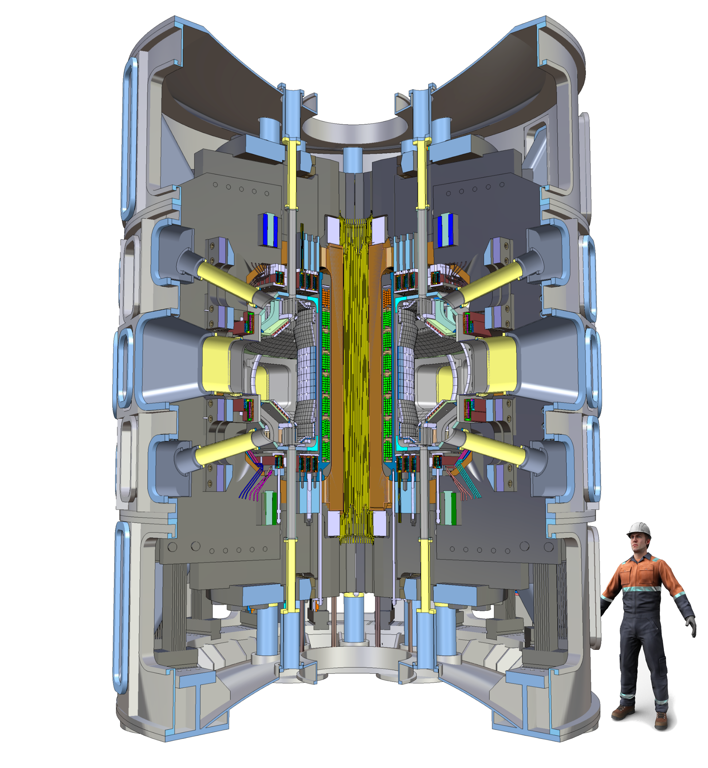
3D view of the COMPASS-U tokamak

Visualisation of the COMPASS-U tokamak inside the experimental hall

Plasma scenarios: lower single null, double null, negative triangularity, snowflake divertor
- Fully metallic (Inconel, W-coated Inconel and W)
- First wall and vacuum vessel operated at high temperatures (nominally 300 °C, up to 500 °C), heated by gaseous He or CO2
- 8 guard limiters made of tungsten tiles
- Support the plasma column during the plasma start-up and termination (~0.4 s)
- Protect the remaining inner wall tiles (Inconel 718)
- 32 tungsten cassettes, bolted to a toroidally continuous outer ring held by 16 flexible supports
- PFC tiles bolted from the cassette back side
- Divertor baffled may be made of with W-coated Inconel
- Heat loads up to ~100 MW/m2 -> heat dissipation is required (detachment, strike point sweeping) to lower the heat fluxes
- Designed to routinely endure 20 MW/m2 for 2-3 s
Tokamak plasma facing components
(tungsten - magenta, tungsten-coated Inconel - cyan, Inconel - grey)

- Made of Inconel 625 stainless steel, up to 35 mm thick
- Total weight: ~9 t (including PSP)
- Supported from the bottom by 8 flexible Inconel 625 beams


- First wall and vacuum vessel will operate nominally at 300 °C, up to 500 °C
- Vacuum vessel is thermally insulated by 20 mm of multilayer insulation (MLI)
- Piping: Inconel 625, welded on the inner side of the vacuum vessel
- Heating/cooling medium: He or CO2 (gaseous)
- Heating power ~40 kW heats the vacuum vessel and internal components to working temperature in ~24 hours
- Cooling power ~33 kW removes the energy deposited by the plasma during the discharge (max. 40 MJ) in 20 min


Heating/cooling pipes Temperature distribution during tokamak operation
Toroidal field coils (TF coils)
- 16 coils made of OFHC (Oxygen Free High Conductivity) copper, CuAg0.1 or CuZr0.1, 7 turns each
- Central solenoid and poloidal field coils inside the toroidal field coils -> the TF coils are dismountable with a sliding joint at the crown and a bolted joint at the outer midplane
- Cooled to 80 K by gaseous He
- Can carry 200 kA of current, producing Bt = 5 T at the magnetic axis (R = 0.894 m)
- Toroidal field ripple at separatrix δ < 0.5 %
- Assuming CuAg0.1 as the TF coil material and sliding joint resistance 0.2 μΩ, during a 3s flat top at Bt = 5 T, the TF coils will heat up by several tens of K -> must be cooled after the discharge

Toroidal field coil system
- 4+4 poloidal field coils and 8 identical central solenoid segments
- Hollow conductors made of OFHC (Oxygen Free High Conductivity) copper, CuAg0.1 (C10700), half or full hard
- Cooled to 80 K by a gaseous coolant (He or H2)
-
Located inside the toroidal field coils
- 1 power supply per pair of CS coils -> 14 power supplies in total
- Conductor insulation: 1 mm S2 glass tape + kapton
- Inter-layer insulation: 0.6 mm S2 glass tape
- Ground insulation: 3 mm S2 glass tape
- Vacuum pressure impregnation using epoxy resin


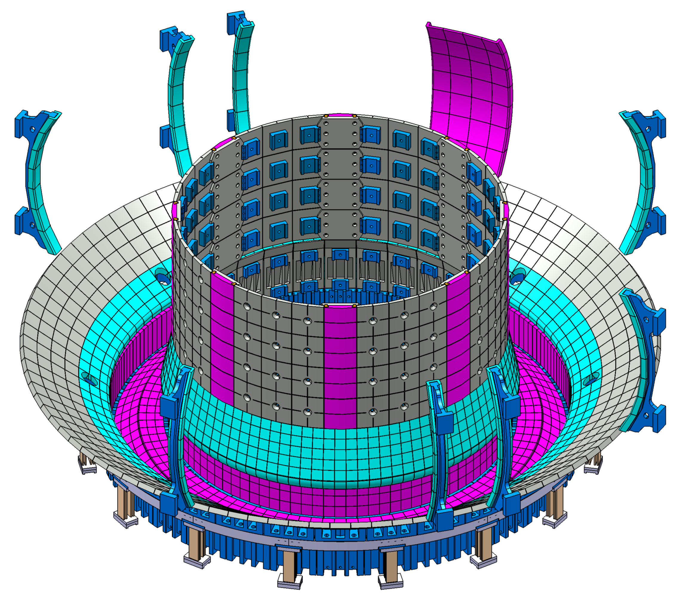
Poloidal field coils and central solenoid placement Central solenoid structure and mechanical loads
Cryostat and support structure
- Stainless steel AISI 304
- Volume ~100 m3, weight ~50 t
- The tokamak is placed on top of the cryostat base
- 8 massive steel supports attached to the 0.8 m thick steel-reinforced concrete slab of the experimental hall
- Multilayer thermal insulation (MLI) on the inner surface
- Material SS 304(L)N or 316(L)N
- Height ~4.4 m, diameter ~4.4 m, total weight ~190 t
- 16 C-frames + flexible supports
- Cooled to 80 K with gaseous He led through stainless steel pipes welded to machined grooves
- Cool-down in ~1 week time, accompanied by vertical contraction of ~14 mm
- Can be vertically disassembled


Cryostat Tokamak support structure

3D view of the support structure
- After a discharge, tokamak systems (plasma facing components, TF coils, PF coils, central solenoid...) must be cooled down; this takes <60 min
- TF coils ~250 MJ, PF coils ~50 MJ -> required cooling power ~100 kW
- Cooling performed by multiple closed gaseous He loops
- CS - high pressure (pbase = 60 bar, Δp = 4 bar, ṁ = 80 g/s)
- PF - medium pressure (pbase = 20 bar, Δp = 1 bar, ṁ = 160 g/s)
- TF - low pressure (pbase = 20 bar, Δp = 0.1 bar, ṁ = 800 g/s)
- Main cold source – liquid nitrogen heat exchanger
- Cycle cooler (Brayton, J-T, G-M, ...) for subcooling under 80 K


Simulations of tokamak systems cooling
Neutral beam injectors (NBI)
- 3-4 MW of NBI power at neutral energy 80 keV, organized in 2 x 2 MW units
- Ions supplied by two ion RF sources above each other, inclined by ~7° from horizontal plane
- The first unit is about to be delivered by BINP Novosibirsk (will be installed on COMPASS)
- Injectors aim between the magnetic axis and the HFS wall - tangency radius R < 0.65 m
- The two existing COMPASS NBIs (each 0.3 MW at 40 keV) will be upgraded and used for diagnostic purposes

- ECRH system enlarges the COMPASS-U operating space and plasma performance
- Deposition on-axis is achieved for Bt = 1-2.5 and 5 T, toroidal steering needed for Bt = 3-4 T
- Simulations in TORBEAM and ASTRA are ongoing
ECRH components
- Gyrotrons: dual frequency 105-140 GHz, 1 MW, pulse length 3-5 s
- Waveguides: 63.5 mm in diameter, total length < ~30 m
- Launchers: large equatorial port, steering mirrors

ECRH operation modes
- has to provide approx. 270 MW of power and 500 MJ of energy
- uses the existing flywheel generators (50 MVA, 50 MJ each) and two new flywheel generators (106 MVA, 195 MJ each)
- Power and energy: 85 MW - 90 MJ
- Based on IGBT H-bridges
- Power and energy 140 MW - 340 MJ
- Based on thyristor converters
- FDR completed in February 2019
- Contract signed in February 2020
- December 2021 - first components manufactured (HV distribution station, flywheel starting motor, transformators, etc.)

Tokamak power supply system schematic